GRAVITY GOODS ROPEWAY
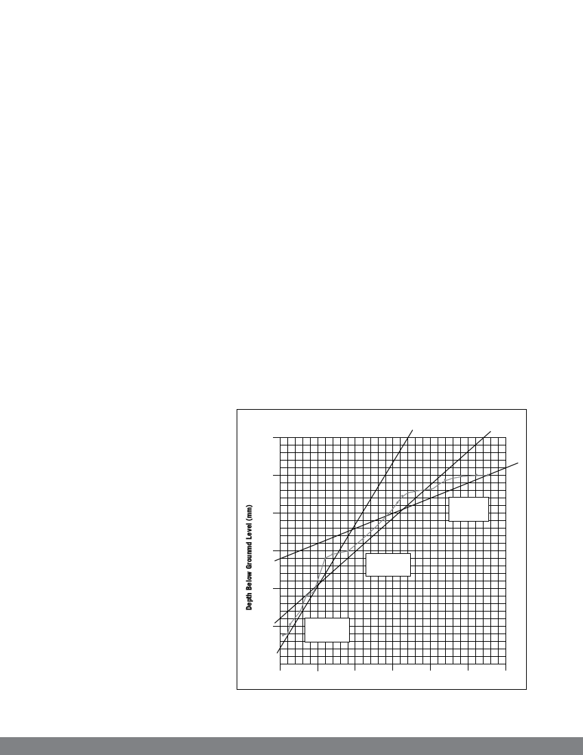
In general, a DCP penetration of 8 to 10 mm
per blow gives adequate founding ground. If
the soil strength is still very low at depths
greater than three metres, then the foundation
should be treated as poor soil. The empirical
relationship between DCP penetration and
equivalent ground bearing capacity are given
in figure 13.
With loose sands and silts, there is a great
danger of the excavation site collapsing,
especially if there is a flow of underground
water. The sides of the excavations should
be braced with timber to avoid the soil from
collapsing into the water. The investigating
engineer should design a suitable and safe
shoring method on the site.
If the water table is high and there is
a continuous inflow of water into the
excavations, the water should be pumped out
using ordinary buckets tied strongly by ropes
manually or through mechanised pumps.
The visual assessment by the investigating
engineer will determine whether disturbed
soil sample needs to be recovered
from the field for further testing
in the laboratory.
3000
laboratory tests of the soil samples. The soil
sample should be tested according to the relevant
code of practice. The laboratory tests will include,
following:
Particle size distribution: This test includes
wet and dry sieve analysis method combined
with the hydrometer analysis for the clay
fraction. The grading envelope will be plotted
from these tests. The coarseness and fineness
index, and clay fraction will be determined
from the particle size distribution test.
Plasticity index test: The liquid and plastic
limit test is carried out to find the plasticity
index.
Free swell test: This test determines the free
swell of the clay samples.
The criteria for potentially active clay is checked
from the above tests. If the soil is expansive, it is
highly recommended to change and relocate the
site for the stations or extensive sub soil treatment
may be required.
Penetration Chart
From the pit, following information
can be collected:
Ground strength
Soil type
Soil graduation
Compactness
Grain shape
Estimation of percentage of
boulder greater than 60 mm
diameter in soil
Ground water condition
Geological domination
2.3.2 Laboratory test
In cases where, on site visual
assessments have shown potentially
active subsoil, the soil activity should
be assessed further by carrying out
2500
2000
1500
1000
500
n=11mm/blow
dp==210.40-k2p.2a m
n=19mm/blow
dp==102.02-k1p.4a m
0 50
Figure 13: Penetration chart
100 150 200
Cummulative Blows
n=3mm/blow
pd=>426.02kmpa
250
300
14